Messing about in boats since 1975. Online Since 1997.
Home | Intro | Our Design Process | Stock Design Info | Motor Yacht Designs | Sailing Yacht Designs | Prototype Designs
Plans List | Articles | Our CAD Design Stream | Maxsurf | SITE MAP..! | Site Search | Design Team | Contact Us
Please see the AVAILABLE BOAT PLANS web page
Computerized Cutting For Boat Building
Copyright 2014 Michael Kasten
Computerized Cutting vs. Manual Construction Methods
What is NC...? It simply means Numerically Controlled...
Even though computerized cutting has been around for boats and ships for several decades now, it is shocking to discover any remaining reticence people might have in embracing this technology. In particular this can be the case among yacht builders.
Fortunately, NC cutting is becoming more and more common and it has become fairly 'normal' to encounter boat builders who familiar with the advantages of computerized cutting. It has almost become completely inconceivable to build a vessel of any size by manual lofting and cutting. For large ships, it just is not done - it's too time consuming and therefore too expensive. At last it seems that builders of smaller boats are willing to embrace this concept - and therefore also reap the benefits...
A number of excellent software tools are available, and have become commonplace even among smaller yards and design offices. In other words, the 'big ship' technology has 'trickled down' to the builders and designers of smaller vessels.
When the remaining 'Luddites' among the small yacht builders at last wake up to this technology, we will all benefit.
The Process...
To create the computer-driven NC cutting files needed for boat building the process will ordinarily be as follows:
First one must create the hull and superstructure geometry by computer modeling, then those surfaces must be faired perfectly. This is most efficiently done within a dedicated yacht design program which will most often make use of NURBS (Non Uniform Rational B-Spline) surface geometry. For an overview of why this is the best approach, please see my article on Why NURBS...?
If the design is one that the designer has created using computer modeling, then the hull geometry will already be in place since the hull model will have already been created as a result of the design process itself.
Once the computerized model has been finalized and faired, the design will then be detailed in a program that is dedicated to generating the vessel's structure. In the past one would have used an ordinary CAD program to perform the structural detailing, most often as a simple "wireframe" model. The disadvantage of this work stream is that, having translated the design geometry from one software program (the surface modeler) to another (the CAD program) the hull design is "frozen" in terms of its shape and cannot thereafter be changed without a fairly large re-investment of time (and consequent increased cost).
This has changed...
Presently there are a number of good software programs aimed specifically at generating boat structure. Modern marine design software is available either as an inter-related suite of programs that are optimized in a fundamental way, or as a series of unrelated programs, each of which is able to accomplish a specific task.
In a few cases, such as with the Maxsurf Suite of programs, the design file can be directly opened within the structure-generating module, in which case the structure detailing does not require that design first be 'frozen' before it is further detailed, and the model may even be changed without undue penalty down-stream. This is the 'best of all possible worlds' for one's work-flow, where the software that created the hull shape in the first place can still alter that shape after the structural detailing has been started...
In the Maxsurf Suite of software modules, Maxsurf Modeler is the surface modeling environment that originates and modifies the design; Maxsurf Stability (Hydromax) is the hydrostatics analysis environment for stability and trim; Maxsurf Motions (Seakeeper) is a hydrodynamics module for analysis of motions, and Maxsurf Structure (Workshop) is the program for creating structure. Each of these software components can open the original surface model and work with it in a familiar, intuitive, shared software interface.
In Maxsurf Modeler one can quickly create, analyze and fair a new boat design, including the hull and superstructure. Then, downstream in Maxsurf Structure (Workshop) one can define the basic structural components: frames, bulkheads, soles, decks, stringers, and plates. Workshop is specialized for this purpose, and is very efficient in use.
The advantage of being able to use the original 'native' NURBS model within each program is that a "parametric" relationship is able to be preserved between the structure that has been assigned to the model and the underlying NURBS surface geometry within the original design file.
Because of this relationship it is possible to edit the shape of the vessel within Maxsurf Modeler at any time, and any changes made to the hull shape will flow through and be re-calculated within Workshop. Thus it is not necessary to "freeze" the design geometry prior to being able to begin the structural detailing. Among the various marine design software packages now available, this capability sets Maxsurf apart from the crowd.
Maxsurf Structure (Workshop) can automate much of the structure creation. For example, within Workshop the frames and bulkheads are defined and are automatically fit to the surfaces. Longitudinal stringers are automatically generated onto the surfaces, dividing the girths as specified. Various shapes and cutouts are assigned to the stringers, and are automatically placed into the frames and bulkheads along the path of each longitudinal or at the edges of the plates.
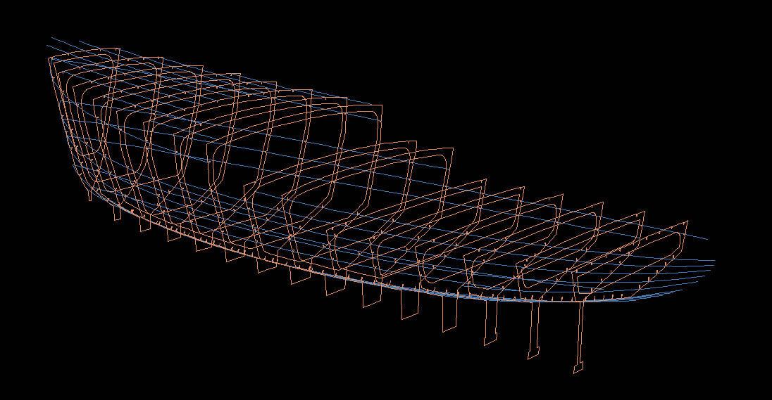
For a simple design such as the one shown below, the generation of the structure within Workshop takes very little time to accomplish...! The surfaces were created in Maxsurf, and the preliminary layout of the frames and long'l stringers were generated within Workshop within a few hours' time. Of course there is considerable work to be done in order to fully detail the parts for cutting, but the genesis of the basic structure is very quickly accomplished.
Maxsurf Modeler provides free form modeling tools for creating developable and non-developable surfaces. In order to expand the exterior plating, Workshop provides a choice of algorithms for determining the shapes of the exterior hull plates. Each of the plate expansion methods within Workshop is optimized for a specific type of hull material, whether steel or aluminum plate, plywood sheathing, or GRP / CF fabric. The ability to pre-determine cloth patterns is especially useful when using pre-impregnated cloth or other high cost fiber reinforcements.
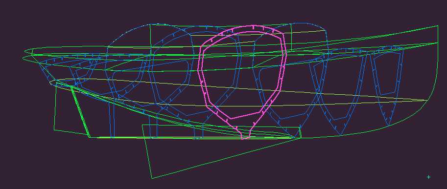
For metal structure, once the structural components and plating have been defined in Maxsurf Structure (Workshop), the parts are exported to a CAD environment for further detailing. The image below shows the structural parts of a motor yacht design after having been exported from Workshop, then imported into Microstation.
Once the structure has been detailed and finalized, it must then be efficiently 'nested' onto the available plate sizes. In other words, after editing and detailing the frames and plates, the structural parts will be broken into smaller segments for efficient nesting. The process is the same whether the parts will be nested onto metal plates or onto plywood sheets.
Once the nesting has been accomplished, the plate definitions are sent to an NC cutter. The AutoCAD DXF or DWG file format has become the de-facto file format preferred by the industry. Since Microstation can easily and transparently open, work with, and save a DXF or DWG file, the standards of the working world are preserved.
When the NC files have been finalized, then they are sent to the NC cutters. Email makes this a rather quick and easy transfer right to the cutter's shop regardless of location worldwide.
GRP mould making is equally suited to this design stream. Planked wooden construction resists being automated to a somewhat greater extent than other hull materials, although it would certainly be an easy matter to create the mold frames and templates to build any wooden vessel using these same methods.
With a GRP or a wooden vessel, the resulting geometry will be sent to a computer driven router. In the case of flat sheet plywood, it is much the same process as would be used for metal parts.
In the case of a plug or mould being created in 3D for a GRP vessel, a 5-axis router can be used to cut the mould shape directly from the surface model.
In everyday use the Maxsurf / Workshop combination has proven to be highly capable, fast, and accurate. For a more complete outline of our actual CAD development process, please check out our CAD Design Stream article.
What's Included?
When we develop our metal boat designs for NC cutting, our 'deliverables' includes drawings to show all the parts that have been detailed. One series of drawings shows the parts as-nested, ready for cutting, another series of drawings shows the parts separated prior to nesting, and a third series of drawings shows the parts as-assembled.
Our NC cut parts include all the frames and plating for hull, decks, superstructure and cabins, as well as all of the internal structures such as tank faces, baffles, lids, engine girders, keels, stem, keelsons, bulkheads and rudders. For larger craft other internals are included where appropriate such as water tight soles, etc. Where needed, "insert plates" are also included. Insert plates are especially important on aluminum vessels, where they reinforce locations of higher stress such as around chain plates, above propellers, around keels, below windlasses and mooring cleats, and so forth.
In all, it is our goal to supply a complete set of NC cutting files that will provide all the parts that relate to the surface shape of the hull. These hull-shape-related parts are those that save the builder the most time, since each part would otherwise have to be lofted and patterned prior to construction.
Our NC cutting files are therefore the "definition" of the parts, rather than being an actual "boat kit" per se. In other words, we do not provide the actual metal or plywood boat parts. Instead, we provide the drawings to the builder and the NC files to the cutter, and then we follow through in order to facilitate the cutting and delivery of the parts to the builder.
Our NC files will always be adapted to the specific requirements of the cutter being used, for example to accommodate inter-part clearances that their machinery requires, or to adapt the NC files to metric vs imperial materials, or possibly to re-size the nestings to accommodate restrictions imposed by a smaller cutting table, etc.
It is our policy to provide a high level of support to the metal cutters for the sake of accuracy, and to assure that the files can be used with a minimum of fuss and bother. For an in-depth peek at what's involved please see our CAD Design Stream article.
Lofting...
As an added benefit of having modeled the lines via computer, one can output the lines (or perhaps just the body view) onto Mylar - or better yet, directly onto the building platen. By this latter method, a builder may choose to completely eliminate lofting and proceed directly to assembling the already cut parts.
Although this may seem odd to traditional boat builders, most builders now prefer to dispense with the lofting entirely. The strategy used in this case is to erect an accurate grid on the building floor, then to simply align the grid that has been marked onto the parts with the "master" grid on the building floor.
This degree of faith in the capability of NC cutting may seem shocking to some (having once worked as a loftsman it was indeed shocking to me at first) yet innumerable builders have proven this method both highly accurate and very efficient.
The Savings
The number of hours involved in creating a custom boat design is not so large when compared to the hours required to actually build the boat. Good design will therefore have several objectives, one of which is to save overall costs wherever possible. It is for this reason that we advocate NC cutting.
Once a new design has been created, the next logical step is to prepare the structure for NC cutting. In so doing, the time invested in generating and fairing the 3D hull and superstructure model on the computer can be leveraged directly into the building process itself.
The number of hours added to a yacht design project to include NC cutting will be compensated for by a reduction in labor during the building process. With a pre-existing design, NC cutting will also permit an overall savings, even if one must first create the computer model for that purpose.
By these methods, we generally estimate that a new custom yacht design can be created, detailed for NC cutting, and built for the same or less overall vessel cost than that of a "hand built" boat using a stock design. Here is some feedback from boat builders:
- Estimates of the amount of labor saved will vary from one builder to another, depending the degree of experience they've had with NC cut boats.
- Professional builders credit NC cutting with being able to effect a 35 to 55 percent reduction in the man-hours required to build the structure. This translates into a larger profit margin for the builder and / or a substantial savings to the owner.
- For an amateur builder, the amount of fabrication time saved can be dramatically greater, since there is not only no lofting and cutting to be done, but there will also be no time spent planning or worrying about lofting or cutting...!
- Even with a professionally built one-off boat the fabrication labor saved will more than pay for the cost of generating the NC files. In particular this is so in consideration of the accuracy of the fit-up, elimination of grinding and shaping parts to fit, and the resulting vastly improved fairness during weld-up.
- If it will be a repeated project, the NC development cost can be amortized over a larger number of projects, and of course there will be much greater savings.
- The cost of developing NC cut parts will depend on the amount of detailing required, as well as the relative simplicity of the design and its structure.
- A vessel that is more complex will be able to effect an even greater savings via computer cutting, more or less in direct proportion to the amount of labor that would have been required had the vessel been lofted, cut and fitted by hand.
In order to control the cost of generating the computer model of a vessel and of developing the parts for computer cutting, it is necessary to know what is sufficient detail... This question must always be answered on a case by case basis, however we can make a few generalizations that will nearly always apply.
- Beyond the obvious benefit of generating the vessel's framing, it is worthwhile to create additional surfaces in the model for tank faces and tops, bulkheads, soles, engine girders, stem, keels, superstructure, and all of the hull plating.
- It is also a benefit to develop any of the smaller fittings on deck or any rigging components that can be cut from flat plate.
- Fittings made from pipe, tube or other extruded shapes are not candidates for NC cutting and will always be cut and fitted by hand.
- Although stringer cutouts are always included in cutting the frames and bulkheads, ordinarily it is not a benefit to include any of the hull stringers themselves in the NC cutting regime since extrusions can be more economically used, and involve very little waste. The exception is any instance where the stringers will have excessive curvature, in which case NC cutting of the stringers will definitely provide a benefit.
A few other generalities should be mentioned...
- The accuracy of the computer model is a critical factor in the success of the whole adventure.
- It is imperative that good software tools be employed and that the software operator has the skill to produce fair and accurate results.
- The vastly improved accuracy of the fit-up of NC cut parts versus hand cut parts will reduce the fabrication time; will result in much less weld distortion; and will produce a much more fair hull surface.
Acceptance
It may be shocking to some who adhere strongly to traditional methods, but computers and software have actually become boat building tools..!
As these tools have become increasingly refined and affordable, the general acceptance of computer modeling and NC cutting has been on the rise. As a result, we now see the nearly ubiquitous use of the NC cutting process, even on smaller projects, whether they are for production or are a one-off build.
The acceptance of NC cutting by yacht builders in the US has lagged behind the rest of the world. This mainly comes down to lack of familiarity (dare we say ignorance..?). It is quite the opposite in Europe, New Zealand and Australia where builders have come to expect that a boat's structure will be computer cut, regardless of size. In recent years we have seen considerable improvement in this landscape, and these days even boat builders in the US have come to acknowledge the benefits of NC cutting..!
In the final analysis, given the excellent software tools available, there is just not a more practical means to build a vessel, whether small or large, regardless of the materials of construction.
Computer Modeling & Analysis Links
Our CAD Design Stream | Why Use NURBS...? | Maxsurf Information
NC Prototyping | NC Parts Cutting | NC Boat Building Advantages
Please see the AVAILABLE BOAT PLANS web page.
Home | Intro | Our Design Process | Stock Design Info | Motor Yacht Designs | Sailing Yacht Designs | Prototype Designs
Plans List | Articles | Our CAD Design Stream | Maxsurf | SITE MAP..! | Site Search | Design Team | Contact Us