Messing about in boats since 1975. Online Since 1997.
Home | Intro | Our Design Process | Stock Design Info | Motor Yacht Designs | Sailing Yacht Designs | Prototype Designs
Plans List | Articles | Our CAD Design Stream | Maxsurf | News..! | SITE MAP..! | Site Search | Design Team | Contact Us
Please see the AVAILABLE BOAT PLANS web page
Why Use NURBS Surface Modeling...?
Our rationale for using NURBS surface modeling for boat design.
Copyright 2012 - 2021 Michael Kasten
As an extension of our article describing our CAD Design Stream, this page outlines our use of NURBS surface modeling to create our boat and yacht designs. The aim here is to communicate the basic rationale for using NURBS surface modeling as opposed to other 3D modeling methods, such as solids modeling for developing any type of 3D free form design. NURBS stands for a "Non-Uniform Rational B-Spline" type of surface. The technicalities of what that means, you can research on Wikipedia. The reasons for using this approach for yacht design are the purpose of this article...
The development of a new boat shape can be thought of as being a series of steps, each of which takes advantage of a different aspect of the original 3D NURBS surface model in a different way, more or less as follows:
1. Creating the Design ...................... (in Maxsurf - now called Maxsurf Modeler - in 3D)
2. Analyzing the Design .................... (in Hydromax - now called Maxsurf Stability - in 3D)
3. Detailing the Design ..................... (in Microstation in 2D)
4. Generating the Structure .............. (in Workshop - now called Maxsurf Structure - in 3D)
5. Detailing the Parts ........................ (in Microstation in 3D using 2D entities)
6. Nesting the Parts ........................... (in Rhino in 2D)
7. Cutting the Parts ............................ (done by the metal cutter in 2D)
8. Building the Boat .......................... (done by the boat builder in 3D)These 'design steps' are outlined below along with the specific reasons for choosing to initiate the model design in a Free Form 3D NURBS Surface modeling environment.
AN APPROPRIATE LEVEL OF COMPLEXITY
It is instructive to consider the question of "What is an appropriate level of complexity for the CAD model...?" This question has been elegantly addressed by Philip Christiansen and Andrew Mason of Formation Design Systems in a paper that compares large ship building CAD systems to workboat and yacht design CAD systems. Philip and Andrew wrote as follows:
When using a CAD system for vessel design and construction, it is important to choose an appropriate level of complexity for the CAD model. The idea that it will always be beneficial to create an entire "product model" of the vessel, complete down to the smallest detail, is not especially applicable to the construction of workboats.
The cost of any vessel incorporates a percentage allocated to the design. The larger the vessel, the more money is available to be spent in the design process, even though this may be a lower percentage of its total construction cost than for the design phase of a smaller workboat. After the bare minimum of design data have been generated, further time can be justified in increasing the level of design detail only if it results in an equivalent saving during the construction phase, or lower repair and maintenance costs during the life of the vessel.
As more detail is modeled in the CAD system, a point will be reached where the downstream savings are outweighed by the additional design costs. This point varies based on the cost, size and complexity of the vessel, the cost of available labor, the level of automation in the shipyard and the number of vessels being produced. For example, if a vessel is a one off design, the amount of detail modeled may necessarily be less than for a production run of many vessels.
It is with this "appropriate level of complexity" in mind that we approach the design of yachts and workboats here at Kasten Marine Design, Inc. In other words, we do not need to model every last nut and bolt as might be desirable for NASA or to design a military submarine... For everyday boat and yacht design, that would be extremely unproductive, wasteful, and costly. Instead, we must engage in a streamlined CAD process that is efficient, accurate, and cost effective.
Toward that end, we have found Direct NURBS Surface modeling to be the sweet spot for boat design. The following notes outline our rationale for having made this choice.
MODELING & ANALYSIS OPTIONS
When comparing the commonly available software tools as they are used for boat and yacht design, it is useful to differentiate between two basic approaches to 3D modeling:
- Parametric or "history based" modeling environments which require advance planning of features, constraints, relations and dependencies within the model. A history of the logical genesis of the model is maintained so that changing a pre-defined parameter changes the model. Some environments allow directly changing the model, which updates the underlying relationship constraints.
- Direct or "free form" modeling environments which allow a more intuitive and flexible "hands-on" manipulation of the model regardless of how or in what sequense the model was created. In many cases relationships can be defined, such as for trimming or to bond surfaces along an edge or to enforce tangency between surfaces, but they are not needed in order to create the model, and they do not affect one's ability to grab parts of the model and push, pull, move, etc.
Along with those two basic types of modeling environment, we must also consider two essentially different types of 3D model.
- Solid models in which all parts are have thickness and are assigned mass properties.
- Surface models which make use of zero thickness surfaces which have no mass properties.
There are many excellent Solid modelers such as SolidWorks, as well as many outstanding 3D NURBS surface modeling environments, such as Rhino or Maya. Most of these tools, including Rhino, are "generic" tools - jacks of all trades - which do not have the specific aim of generating boat designs. They are instead general purpose industrial design or artistic modeling environments.
What follows is a brief look at the pros and cons of Parametric vs Direct modeling environments, as well as the relative benefits of Surface vs Solid modeling.
RHINO..?
Rhino is a Direct (free form) NURBS surface modeler. All entites in a Rhino model are NURBS surfaces, even down to the text and dimensions, etc.
Rhino can also work with solids even though that is not its essential functionality. Rhino works with solid models by "faking it" as a collection of surfaces that are "tied together" which Rhino refers to as a "polysurface." If a polysurface fully encloses a volume, it is considered a solid and can be assigned mass properties.
Rhino has become very popular as a boat design tool. That has occurred primarily because it is relatively inexpensive as compared to most other modeling solutions, and because it supports many third party plug-ins. Rhino can do some pretty amazing operations on surfaces, such as to create a variable radius fillet between two surfaces. Rhino has many other excellent tricks and its open architecture makes Rhino very flexible, but there several key differences between Rhino and Maxsurf that should be realized...
Rhino and Maxsurf both support meshed surfaces. While meshes are not sufficiently accurate to create a faired smooth surface for actual production, meshes can be useful for data transfer into Maxsurf in order to automatically generate surfaces, and for further analysis of a model within Hydromax.
Although one is certainly able to design boat shapes in Rhino, it was not created for that purpose. There are several plug-ins available that can do basic hydrostatics. The most comprehensive marine design plug-ins are from Orca3D. Although these do not bring Rhino anywhere near the level of functionality in Maxsurf and Hydromax, they are very good tools.
The most fundamental drawback to using Rhino to originate a design is that surface trimming becomes an unforeseen impediment. The reason is that Rhino uses "static" trimming, which means if you trim two surfaces, then move one of them, you have to "un-trim" the prior trim region and recreate it anew. If you have a model with a hundred surfaces or so, you are left to figure out for yourself which ones might have been affected by the surface that was moved, and then edit them one by one. This alone is pretty much a deal-killer in terms of my own use of Rhino for creating new designs.
A further inconvenience in Rhino is that both halves of the model must be managed separately. In other words, the design is not automatically "mirrored" across the centerline, so if you make a change in one half, you have to edit the other half in exactly the same way. Certainly one can just model half of the boat, then manually "mirror" the result, but it is not automatic, nor is it dynamically visual. I believe the Orca3D plug-in addresses this shortcoming as do other Rhino plug-ins available from third parties, however they do so at a price. In other words, the mirroring functionality, lines drawings, and hydrostatics calculations are not part of Rhino itself, but must be purchased separately.
Yet another complication with Rhino occurs when you create a part using an automated Rhino tool, say to extrude a shape along a path (possibly to extrude a pipe along the top of a sheer line) or to create a fillet between adjacent surfaces. Rhino can do these tricks extremely well, and also accurately, however the resulting parts will have an inordinately complex control net, making it extremely difficult to edit down-stream if you wish to still maintain fairness. Effectively this means that if you change the original geometry, say to revise the sheer line, you must delete the extruded part and re-create it.
These factors are all drawbacks when creating or editing a model where global shape changes are inevitable and on-going, as is always the case when originating a new design. The upshot is that while Rhino is an outstanding tool for detailing a design AFTER the shape has been finalized, it falls far short of being an optimum tool for originating the model.
SOLIDWORKS..?
SolidWorks is a Parametric (history based) Solid modeler, in which all parts are given thickness and mass properties in addition to being assigned a parametric relationship to other parts. As such, SolidWorks "fixes" several of the above issues by requiring the creation of a parametric "assembly" or "logic tree" that establishes and preserves intelligent relationships between all of the parts. This in itself imposes a considerable added dimension of complexity. Ordinarily this means the user must construct the various logical relationships in advance, and then manage them while building or changing a model.
The primary utility of software like SolidWorks resides in this very ability to manage complex changes gracefully. SolidWorks is the perfect tool for creating machines, where if a piston diameter is logically related to the cylinder diameter and cooling galleries, if you change the piston, the rest is automatically updated per those relationships.
SolidWorks is a powerful tool for detailing a boat's structure, thereby instantly knowing the global weight and center of gravity. In SolidWorks, even if you have accurate mass information, an accurate CG, and an editable model via its parameters, it may not be fair and you will not have any hydrostatic properties for the shape itself.
For the purpose of originating boat shapes, the resulting model can quickly become inordinately complex. The above described "appropriate level of complexity" must be kept in mind.
When attempting to model free form shapes such as a boat, this approach puts the cart before the horse. When originating a design, it is preferable to remain unfettered by one surface having to be related to another, i.e. not to worry about what effect changing one surface might have on another surface, say if they are tied together and required to move together as is generally the case in Solidworks.
In addition to its very robust solid modeling abilities, SolidWorks also has surface modeling tools. I do not know whether trimming in SW is "static" like Rhino or "dynamic" like Maxsurf. In all probability, it is parametrically defined, therefore dynamic. More on this below...
MAXSURF MODELER..!
Our preference for using Maxsurf Modeler to generate new boat designs is not only because Maxsurf is a unified suite of programs specifically developed for that purpose, but also because the approach taken within the Maxsurf modeling environment makes ultimate sense.
Maxsurf is a Direct (free form) NURBS Surface modeling environment wherein surfaces are used to define an envelope for fairing and analysis. Unlike with Solid modeling, thickness is not a property of NURBS surfaces or splines: they have zero thickness. Unlike SolidWorks, Maxsurf does not require that relationships be established between surfaces, nor does Maxsurf preserve a model construction history. Maxsurf does however allow certain relationships to be created between surfaces, such as trimming, edge bonding, tangency between surfaces, etc.
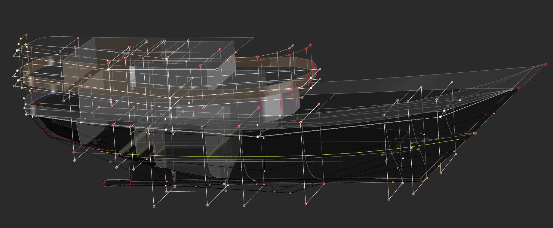
Working with a 3D NURBS surface in Maxsurf is no different than working with a 2D or 3D spline. In Maxsurf we are using a "control point net" as opposed to a series of "through points." In Maxsurf, a surface is defined by a network of control points embedded in a control net that is used to define the surface. The image below is an example of a fairly complex model generated within Maxsurf, with all surfaces trimmed to their final shape and "unlocked" so that the control net is visible. Though the model is complex, the underlying control net is quite simple.
40 Meter Pinisi Charter Yacht as Viewed "Unlocked" in Maxsurf - Click for Larger ImageHaving ruled out Solid modeling as a tool for originating boat designs, we are left with Surface modelers to consider as being the best CAD tool for designing boats. Although Maxsurf can do many of the same modeling tricks that Rhino can do, Maxsurf provides several key advantages...
Modeling: In the above image, you can see that Maxsurf only needs to model one half of the vessel since the other half is automatically and dynamically mirrored across the centerline. If you specifically want asymmetry, that can be set as a property of any surface, so that a differently shaped surface can be modeled on the other side - say for designing a proa. In the image above you can also observe that when modeling NURBS surfaces, there is a great benefit when the control net is kept as simple as possible, whereby fairness is easily achieved.
Trimming: Maxsurf uses "dynamic" trimming. This means that if you trim a few surfaces using a spline or another surface, and you then move one or more of those surfaces or the spline, all of the affected surfaces are all dynamically re-trimmed on the fly. Naturally, this is computationally intensive, and that’s why Maxsurf allows you to turn trimming on or off globally (as in the above image). With trimming off, you can move surfaces and splines around quickly. With trimming on, and precision set to high, it can take a few moments for Maxsurf to figure out all the correct trim regions after each change. If the model is complex, this can take several moments even on a fast machine, but rarely more than a few seconds. As a middle ground, precision can be set to a lower value so that trimming can be displayed correctly with updates calculated quickly, then subsequently set to high precision for final output.
Tools: Although NURBS surfaces have zero thickness, it is possible to set surface thickness properties in Maxsurf. This does not add another surface, nor does it create a solid, but is useful in order to accommodate planking thickness so that the lines and offsets output will correctly account for the planking deduction / addition, taken normal to the surface that has been modeled. Setting thickness and materials properties in Maxsurf also allows those properties to be recognized by Maxsurf Structure (Workshop), the construction module in the Maxsurf Suite.
Maxsurf allows the surface stiffness to be varied in either direction, and allows the control point weights to be varied as needed in order to exert more or less local control over the surface locally. Maxsurf has excellent tools for creating and editing splines, which can be used for trimming surfaces. Maxsurf can create extrusions along an edge or spline or create lathe turnings around an axis using any spline shape.
Maxsurf can create surfaces from cloud data by first automatically creating a series of editable splines and edges, then automatically lofting a surface to those curves. Alternately, Maxsurf can fit a collection of fair surfaces to a set of proven offsets, say to accurately reproduce the shape of an existing vessel.
Fairing: Maxsurf has excellent fairing tools, such as curvature porcupines, Gaussian curvature analysis, rendering, longitudinal compression, etc. as well as tools for automating the manipulation of control points, e.g. align controls to plane; align to vector; smooth control points; smooth patch; rotate / size / move / duplicate / mirror surfaces or splines or controls.
Visualization: In addition to the standard profile, plan and body views, Maxsurf shows a perspective view which can be rendered nicely. Colors, transparency and lighting can all be varied as needed. In each view the grid and the resulting lines on the vessel's surface can each be turned on or off. If the surface is moved, the sections, buttock lines and waterlines are all dynamically updated in all views.
Parametric Variation: Maxsurf is able to automatically iterate a model according to parameters that you set, such as to achieve a specific prismatic or block coefficient, or a given displacement, water plane area or wetted surface, etc. Restraints can be defined, such as to disallow changes to the sheer line, beam, draft, displacement, and any of the other parameters, as long as sufficient degrees of freedom remain to achieve the requested variations. This parametric variation capability allows one to create a family of 'candidate' hull shapes each having slightly different characteristics, which can then be analyzed as to their performance relative to each other, or to specifically stated design requirements.
Tri-mesh Surfaces: Maxsurf can create meshed surfaces, which can be useful for quick modeling and data transfer into Hydromax or other CAD systems. As an example, Maxsurf can automatically fit a meshed surface over a cloud of data. While a meshed surface is not sufficiently accurate for a lines drawing or to make parts from the meshed surfaces, it is adequate for hydrostatics analysis in Hydromax. A meshed Maxsurf model can be created quickly, and can then be opened directly in Hydromax for a complete stability and trim analysis.
Analysis: Maxsurf provides upright hydrostatics analysis, instantly available within the program. A built-in fully programmable calculation sheet is also available, allowing nearly any parameter to be re-programmed and automatically calculated from the basic upright hydrostatic information, e.g. target sail area / VCG / Dellenbaugh Angle, optimum velocity / fuel capacity / endurance, etc. The model can be set to a variety of metric or imperial units without imposing any changes on the underlying geometry. This allows rapid switching between measurement systems during design development.
Model Data: All of the trimmed surface areas and centroids are calculated within Maxsurf, and are available in a data window to copy and paste into Excel. Maxsurf also calculates the x-y-z 'extents' of each trimmed surface. If it is desired to do so, there is a Maxsurf Automation interface by which this can be done automatically with each iteration of the design. Since surface properties such as thickness, materials, and area weights can be assigned within Maxsurf, when calculating the areas and centroids of surfaces, the Mass Moment of Inertia (units^4) is also calculated for each surface, as well as the summary Moment of Inertia for the whole design, which data is useful for analysis in Seakeeper (Maxsurf Motions) and for other analyses of vessel motions and comfort.
Data Exchange: All Maxsurf modules share a common file format. As a result there are zero file translation issues when opening the Maxsurf model in any of the programs in the Maxsurf Suite. The Maxsurf model is opened directly by each of the software modules.
Data Import: Maxsurf can import background images for each view in the gif, jpeg, png, and bmp format for modeling a pre-existing design. Maxsurf can import DXF polylines in any view for precise modeling to a known shape. Maxsurf is also able to import whole designs using the Rhino Open NURBS *3dm format, or IGES NURBS surfaces.
Data Export: Maxsurf and Hydrolink support 3D NURBS data export via IGES, IMSA NURBS, Fastship, and the Rhino Open NURBS *3dm format. A host of CFD and hydrostatic analysis export formats are also supported, including GHS, Autohydro NUSHALLO, etc. Maxsurf can export to 2D or 3D DXF polyline, face or mesh geometry (AutoCAD) to a high level of precision. Tabular data such as hydrostatics and surface areas can be directly copied from Maxsurf and pasted into Excel for further analysis.
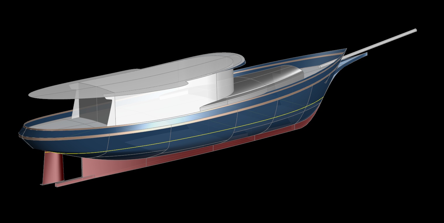
80' "FANTAIL STEAMER" Style Yacht as Viewed in Maxsurf - Click for Larger Image
MAXSURF STABILITY (Hydromax)
Within Maxsurf Stability (Hydromax) one can define tanks, which ordinarily use the hull envelope as the outer perimeter, though internal surfaces can also be used. Within Hydromax the mass of the tank contents is defined, and for each load case what percent of liquid is in the tank.
Hydromax then heels the model, moves the tank contents to the trim of the vessel at each heel angle, recalculates the CG based on the new position of the tank contents, and erects a righting arm for that heel angle. Over the range of heel angles, the righting curve is created. Built into Hydromax are all worldwide stability criteria, from which Hydromax will create a detailed pass-fail report based on the criteria that you select.
During the genesis of the design, since Maxsurf does not have any "structure" information aside from surface materials (say, plating) the surface areas and centers are exported to Excel, where a weight per square area for each surface can be assigned in order to get the CG of the structure. In combination with a thorough list of equipment weights and their centers, tank contents, etc. an accurate CG is obtained.
With the weight and CG information being generated in Excel concurrently with the actual Maxsurf model, we can iterate the model shape in order to achieve the requisite trim and stability, or we can edit the location of equipment, tanks and ballast as needed.
With an owner involved in the decision stream during the genesis of the design, numerous changes are inevitable and are to be expected. Thus the design ordinarily goes back and forth between Excel and the various Maxsurf programs a few times before the best solution is found.
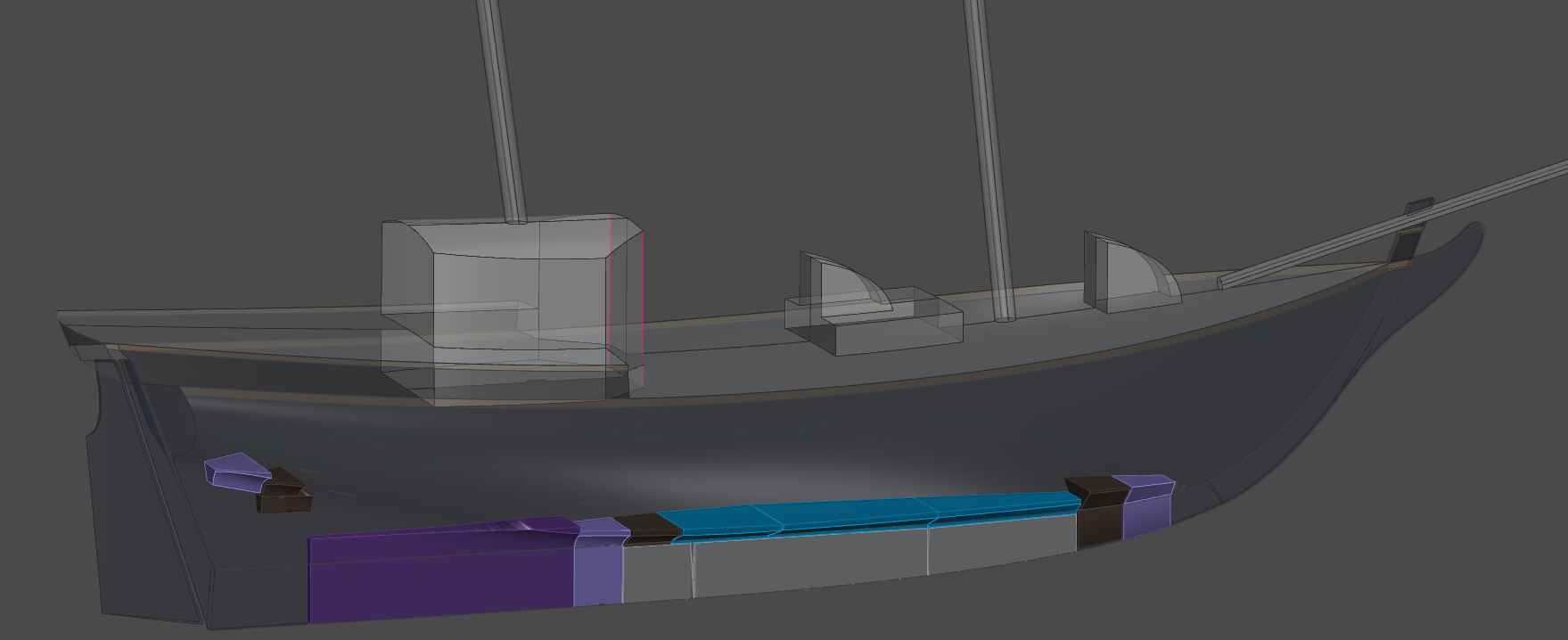
The 61' Brigantine MERMAID as Viewed in Hydromax - Click for Larger Image
MAXSURF STRUCTURE (Workshop)
Maxsurf Structure (Workshop) is not a Solid modeler. Instead, Workshop is a Parametric modeler which enables one to create frames and stringers that are parametrically related to the underlying NURBS Surface model. Even though the structures that one defines in Workshop are "tied to" the surfaces, Workshop is not a history-based modeler, i.e. there is no logic tree or model genesis history maintained. Yet if the surfaces get changed in Maxsurf for any reason, when the design is re-opened in Workshop, all parts of the structure can be instantly re-calculated so that they automatically flow to the new shape without having to be re-defined.
Workshop includes a comprehensive sections library as well as a standard materials library. Therefore once the structure has been defined, one ends up with accurate mass properties based on the materials and sections that we have assigned to the parts, as well as an accurate weight and CG for the model. The Workshop weight table can be exported directly to Hydromax for use as a loadcase, or can be exported to Excel for a much more accurate weight and CG for verification of our preliminary weight calculation.
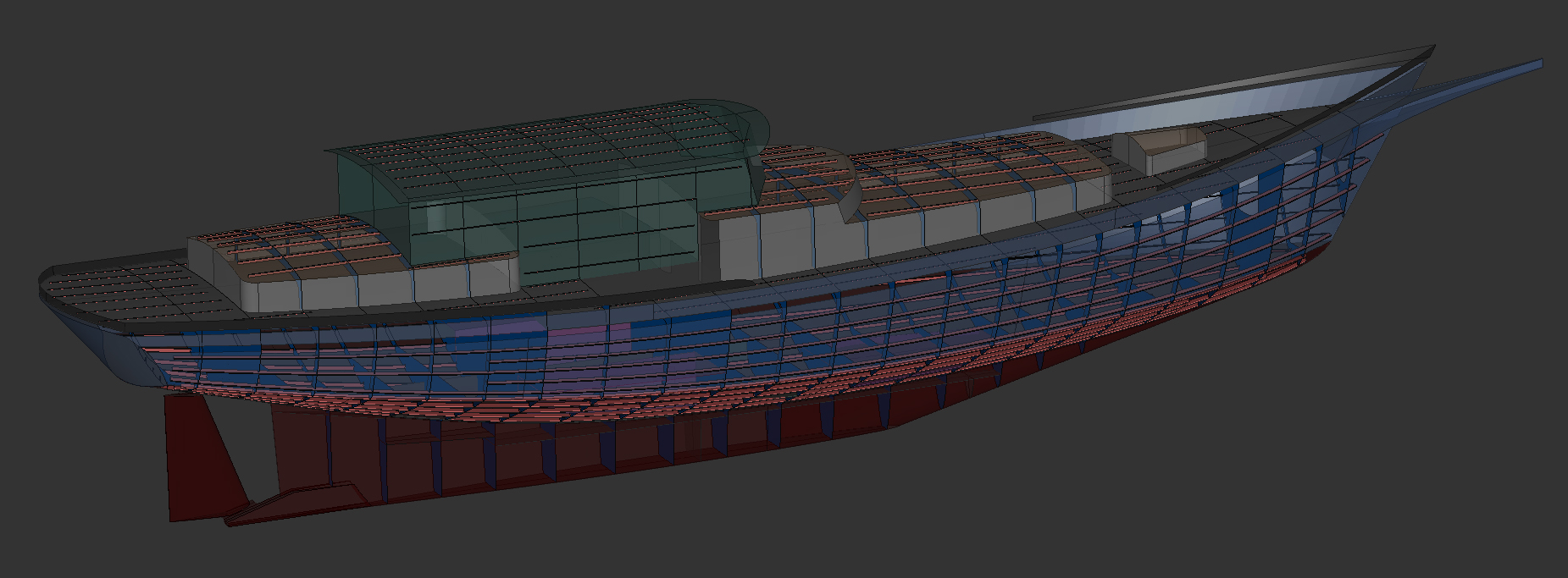
The 56' Ketch SHIRAZ as Viewed in Workshop - Click for Larger Image
MULTIFRAME
Determination of the adequacy of the structure is usually done in Excel by programming the appropriate Classification Society Rule or other structural criteria into a spreadsheet. For more information about how we use the ABS Rule to advantage, please see our article on Designing Boat Structure.
For a preliminary calculation of the overall weigts, once we know the required plate thickness and the associated frames and stringers, a "generic" weight per square area is found for each region (bottom, sides, deck, house, bulkheads, tanks, etc.). With the accurate square area and centroid derived in Maxsurf for each surface, and the weight per square area calculated in Excel, the resulting CG is fed back into the loop, with revisions of the hull model as needed.
As an alternative means of calculating the adequacy of structure, the Workshop structure model can be exported via DXF to the Multiframe module for a first principles analysis of the plating panels, the frames, stringers, or any other details of the strucure. Multiframe can also be used to analyze individual component properties independently, for example to analyze the loads and the resulting strain within the rig (shrouds, masts, etc.).
MAXSURF MOTIONS (Seakeeper)
If it is desired to analyze a vessel's dynamic behavior, Maxsurf Motions (Seakeeper) is used. For this, the surface moments of inertia from Maxsurf are entered, plus other loadcase weights as needed, and SK will calculate the accelerations in a variety of standard sea states. Although I use the Seakeeper program, it is rarely within a yacht owner’s design budget to indulge in this level of analysis. For workboats and high speed craft however, it is highly useful.
As an alternative, roll period, pitch, heave, etc. are readily calculated in Excel using basic formulae published within the volumes of Principles of Naval Architecture. Although the results are not nearly as thorough or accurate as would be calculated by Seakeeper, they are quite useful for comparing one design to another.
OUR PREFERRED PROCESS...
We can see from the above that once the model has been created, Maxsurf is used first to check that the Surface model is fair and that the trim regions are behaving correctly. Then still within Maxsurf, the upright hydrostatics can be quickly checked in order to provide feedback for editing of the shape, and materials properties can be assigned for use down-stream in Seakeeper and Workshop.
Once the preliminary model is nearly finalized, Maxsurf can calculate the surface areas and centroids for export to Excel, where weights per unit of area can be introduced and the CG determined.
Throughout the modeling and stability analysis, none of the internal structure is present in the model, however bulkheads, soles, tank faces, girders, etc. can be introduced in order to have their surface areas calculated by Maxsurf, and for use as boundary surfaces for tanks in Hydromax. All other structure such as framing, stringers, insert plates and other structural components can separately be accounted for in the Excel Weight Analysis, which will provide the overall CG for use in the hydrostatic and large angle stability analyses.
After the design has been finalized, if the vessel will have its parts pre-cut the original Maxsurf model can be directly opened in Workshop in order to begin creating frames, stringers and plates based on the surfaces present in the model.
This arranges the design process in a logical order… i.e. first the desired faired surface shapes are created and basic hydrostatics are performed in Maxsurf, then the CG is calculated in Excel, then the large angle stability analysis is performed in Hydromax, then the Maxsurf model can be edited as needed according to those results.
Once the design is "fixed" or nearly so, the Maxsurf model can be brought directly into the Workshop Parametric modeling environment in order to create the internal structure and expand the shell plating. This is all done without file translation by direct use of the faired Maxsurf Surface model.
To review this design process in greater detail, please see our Design Stream article. To see our design process in flow-chart format, please see our Design Flow Diagram.
FILE CONVERSION HEADACHES...
Maxsurf is able to directly export the Maxsurf model to the Rhino *.3dm file format. Since both programs are free form NURBS Surface modelers, a Maxsurf model exported to Rhino will open flawlessly in Rhino. Maxsurf provides a Maxsurf Plug-In for Rhino, which allows the Maxsurf Assembly Tree to be preserved for use in Rhino, as well as when subsequently opening the *.3dm Rhino file within Maxsurf. If the model is not embellished too much in Rhino, bringing it back into Maxsurf ordinarily works very well.
However if the model has been substantially enhanced or detailed in Rhino, there can be entities that Maxsurf will not recognize which will be deleted from the model on import to Maxsurf. Examples are any text or dimensions added in Rhino; complex entities such as ports; mechanical items, etc. For the most part though, since both Rhino and Maxsurf are inherently surface modelers, the round trip between programs works well for the basic surface model.
Rhino is hands down the best CAD program available for translating one CAD format into another. For the most part this works well when bringing various CAD file formats into Rhino. However it can be problematic when trying to use Rhino as a possible intermediary in order to translate one kind of CAD model into another format -- for example to get a Solid model into Maxsurf. This is not a failing of Rhino, it is just that the originating software may have created a model that is not compatible with Maxsurf.
For example, a SolidWorks "solid" model (with thickness and all) can be opened in Rhino using a variety of CAD file formats including the SolidWorks native format which Rhino can read rather well. Another option might be to export the SolidWorks model in an intermediary file format such as STEP or STL. While these all open faithfully in Rhino, on attempting to export such a model into Maxsurf, even if converted to NURBS, the original parametric relationships between surfaces will be lost, trim regions defined in the Solid model will not be respected, the surfaces will ordinarily have far too complex a control net for editing within Maxsurf.
The result of trying to get a SolidWorks Model into Maxsurf via Rhino is that when it is opened in Maxsurf there are several surfaces present for each part which "illustrate" the thickness of the part, and which enclose the edges, but there are no mass properties present. In other words the model no longer contains "solids" but instead just contains a collection of surfaces that are unrelated to each other except by their proximity. Further, the SolidWorks generated model is rarely fair and the surfaces often do not even match at their edges.
At this point, in order to be of any use in Maxsurf, or if a hydrostatics analysis will be done in Hydromax, there will be considerable work to be done in Maxsurf to delete all of the non-essential surfaces, possibly involving re-modeling the vessel from scratch in a NURBS modeling environment such as Rhino or Maxsurf (where it should have been done in the first place). The net result is a lot of wasted time and effort.
It is possible that within SolidWorks a zero thickness NURBS Surface model can be created without having to first create a Parametric 'logic tree' or a Solid model. If so, it might then be possible transfer the NURBS Surface model to Maxsurf via IGES or via Rhino using the .3dm file format (both of which Maxsurf can read) for analysis.
Even if that were a possibililty, SolidWorks appears to have several shortcomings with regard to Surface Modeling. For example, according to information from SW users it is not possible to expose nor to directly manipulate the surface control net in SolidWorks, since that would violate the history based parametric relationships among parts. Further, SolidWorks is not able to write to a .3dm Rhino file, so that basically leaves IGES as the only viable avenue from SW into Maxsurf unless Rhino is used as an intermediary. Either way, the result will likely require quite a lot of time consuming re-work in order to re-trim the surfaces within Maxsurf prior to being able to move the model into Hydromax.
The upshot is that SolidWorks or any other Solid modeling environment is inordinately complex for the basic task of creating a fair NURBS Surface envelope.
This is the essential rationale for the Preferred Process outlined above, i.e. starting with a relatively simple trimmed NURBS Surface model generated within Maxsurf which can then be properly analyzed in Hydromax, eventually progressing to a Parametric structure model created within Workshop, and then down-stream to a 3D layout or parts editing environment where the model will be easily received, say within Rhino, AutoCad, Microstation or SolidWorks.
Unfortunately this process DOES NOT work at all well in reverse... for example to get a complex parametrically generated "solid" model into Hydromax for analysis...!
ALTERNATIVE YACHT DESIGN SOFTWARE
Are there shortcomings to modeling free form shapes using NURBS...?
Since any NURBS surface must always be a four sided patch, it turns out that yes there are..! Some shapes are just not that easy to model using NURBS Surfaces.
MULTI-SURF
One non-NURBS Surface modeling program of possible interest is MultiSurf by AeroHydro. MultiSurf is a Parametric Surface modeler that uses Relational Geometry (RG), employing various types of points, curves and surfaces to define key shapes such as the sheer, centerline profile, stem, transom, midsection, etc. Among those entities, parametric relationships are established to assure that they will move together and remain "related." By this means, MultiSurf allows one to build a non-NURBS Surface model using multiple types of interrelated elements. It is a powerful approach.
Parametric "logical relationships" must first be established in MultiSurf, similar to the "assembly tree" used in SolidWorks. The similarity between MultiSurf and SolidWorks is so close that a specialized version of MultiSurf has been developed for the SolidWorks environment, called SurfaceWorks... essentially a more CAD oriented clone of MultiSurf without its hydrostatics analysis capability.
Though modeling with MultiSurf is a relatively more complex process, Relational Geometry is capable of extreme accuracy. John Letcher, creator of MultiSurf, presents a favorable case for using RG modeling especially where a CFD analysis will be required down-stream.
It should be emphasized that the surface model created by MultiSurf (and SurfaceWorks) is not a NURBS surface model, rather it is a relational Parametric model composed of a variety of interrelated points, curves and surface types. Unfortunately the relational model that is created is not recognized within most common CAD systems, nearly all of which have standardized on NURBS surfaces. Thus, in order to be used in other CAD systems the relational model must first be transformed into a NURBS surface model. Fortunately though, MultiSurf includes very good tools which automate the NURBS creation process.
The NURBS model that results is not precisely the same as the original MultiSurf relational model -- rather it is a very close approximation. Unfortunately though, the bi-directional file transferability between MultiSurf and other CAD systems is lost -- in other words it is a one way street from MultiSurf to NURBS to CAD. Presumably if one is working entirely within a SurfaceWorks / SolidWorks environment this may not be an issue. Thus if SolidWorks is one's preferred CAD environment, MultiSurf may well be the Surface modeler of choice.
Certainly if it were necessary to analyze the hydrostatics and stability of a MultiSurf model in Hydromax or another NURBS based environment, it will be easily accomplished, since the degree of precision in the NURBS approximation created by MultiSurf will not make any difference to the analysis.
One caveat though is that in creating a NURBS approximation of the underlying relational model, in my experience with any MultiSurf generated NURBS models, the resulting NURBS control net is inordinately complex, making any down-stream editing nearly impossible if any semblance of fairness is to be preserved. In other words, another one-way street.
If the destination format will be NURBS based for the sake of compatibility with general CAD systems, the question arises: "Have we exceeded the appropriate level of complexity required to create the model, analyze it, and build from it...?" I don't know the answer, although I recognize that the MultiSurf system is well liked by many.
T-SPLINES
Another program combination that overcomes many of the shape limitations of NURBS is the AutoDesk T-Splines plug-in for Rhino, which allows three, four, or multiple-sided patches to be modeled. While there are other modelers that can do this, one key difference is that T-Splines can accurately convert the T-Splines model into NURBS surfaces for use in other CAD programs.
Per my own observations, the resulting NURBS Surfaces are actually quite usable. Even so, the same caveats apply, e.g. since other CAD systems do not recognize T-Splines, exporting a model to NURBS is a one-way street, although certainly the NURBS Surface model can be brought back into the Rhino / T-Splines environment for further editing or detailing.
And of course Rhino must be paired with other third party software such as Orca 3D for any semblance of functionality as a tool for boat design and analysis.
KEEPING IT SIMPLE...
In the Preferred Process outlined above, we are working entirely within the Maxsurf Suite of programs in order to create and analyze the design, and to detail the basic structure. Thus, there is no file translation required, and we therefore experience zero file format translation issues from one Maxsurf program to the next.
But there may be occasions where a model will have originated elsewhere. A model originally created in another NURBS surface modeling environment such as Autoship or Fastship can be imported directly into Maxsurf, or alternately imported via IGES, say for analysis in Hydromax. Some entities in those programs (knots for example) are not supported in Maxsurf, and will therefore be dropped on import, possibly requiring some re-modeling in Maxsurf to return the model to its intended shape.
A Rhino originated model will open reliably in Maxsurf provided that the Rhino model is kept simple. This does not mean the number of surfaces need to be restricted in Rhino, only that entities which do not exist in Maxsurf should be avoided (text, dimensions, solids, etc.).
The inevitable conclusion is that if a NURBS Surface environment will be the eventual destination for the design, the most efficient path will be to originate the design using NURBS Surface modeling.
DETAILING THE MODEL
I use Microstation as a tool for detailing and illustrating a vessel's layout and structure. AutoCAD is more or less equivalent, and is by far the most common CAD program in use. And at long last AutoCAD 2012 is finally able to recognize NURBS... a feat that Microstation has been capable of doing since day one...!
DRAWING THE LAYOUT
Presently I find it faster to work in 2D to create the Building Plan Drawings, especially since they will ultimately be output to 2D plots on paper or as 2D PDF files. To achieve this, first a "fixed" set of 2D lines are exported from Maxsurf as 2D DXF files, then the lines are brought into Microstation for further detailing. Admittedly, in light of the above discussion of 3D modeling, working in 2D might seem primitive, but it is relatively quick to achieve, and since the output must be in 2D anyway, there is not much to recommend against it.
An exception would be if it is desired to create a 3D model for a photo-realistic presentation or as a 3D "walkthrough" or in order to prove that the spaces in the layout are as intended. This can be helpful, but the time required in order to create a detailed 3D layout model -- and the resulting cost involved -- are ordinarily difficult to justify for yachts and workboats of less than around 60 to 80 feet.
If a detailed 3D layout model were the goal, in all likelihood Rhino would be the program of choice, as it would still allow the basic NURBS model to be brought back into Maxsurf for refinement or analysis.
DETAILING THE PARTS
If a design will be detailed for NC cutting, I will use Workshop to generate the basic structure model, including frames, stringers, bulkheads, plating, etc. I will then export the structural model to Microstation in order to refine, edit, detail and prepare the 3D parts for production. For this, I prefer to work in 3D, which results in a model that can be used for illustrating all the parts. The following image shows a screen shot of a vessel's structure from within Microstation.
The VALDEMAR 53 Structure as Viewed in Microstation, Ready for Nesting - Click for Larger Image
A cool 3D Structure Drawing in PDF format shows the same design, output directly from Microstation to a 3D PDF. You can rotate, pan and zoom the 3D model in the PDF, and you can also turn on and off the various layers in the model. This is an excellent illustration / visualization tool for communicating the structural arrangement to the builder.
Although I have no doubt that Rhino could be used equally well for the 3D parts detailing downstream from Workshop, I am much more familiar with Microstation. As a result I do not use Rhino except as an occasional tool for creating an interesting illustration of the model, as CAD translating tool when needed, and as a nesting tool after the parts have been fully detailed within Microstation. This latter trick is made possible by Rhino’s open architecture and the various readily available plug-ins such as Rhino Nest.
CUTTING THE PARTS
Note that NONE of the above described 3D modeling and detailing regime involves a "Solid" model. The third dimension is not needed for actually cutting the parts. It is only necessary to define the 2D "outline" of each part so that it can be used in a 2D environment for cutting. This works quite well using NURBS surface modeling.
In other words, we have employed an "appropriate level of complexity" and no more.
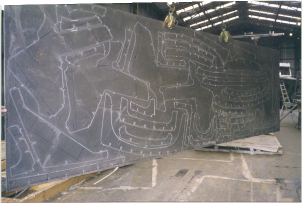
NC Cut Parts for the 25' BOOJUM Tabbed to Sheet for Easy Shipping
BUILDING THE BOAT...!
After all the parts have been cut and shipped to the builder, naturally it is all moved back into a 100% 3D environment...!
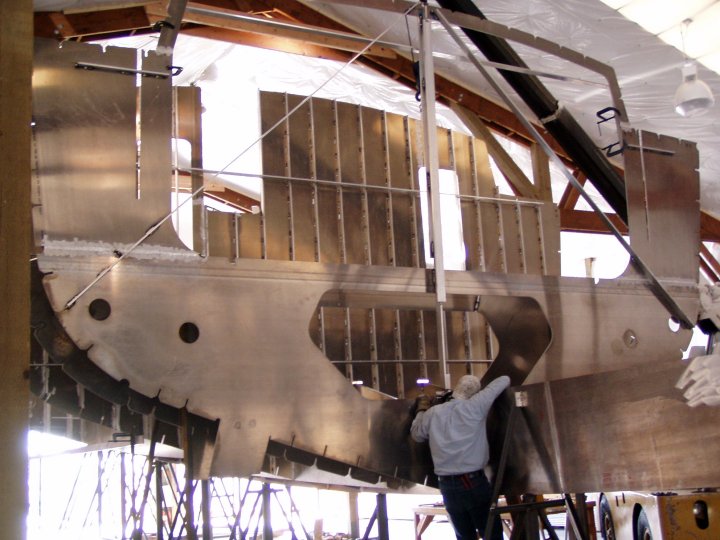
Our 96' Schooner ZEBULUN design, in Frame
DESIGN INFORMATION
Please see our CAD Design Stream article for a complete description of how we implement the above software solutions to create our boat designs and to generate NC cutting files in order to pre-cut a boat's structure.
Although we regularly develop NC cutting files as described above and in the CAD Design Stream article, we do not sell "parts kits" per se. In other words, we do not sell any pre-cut materials. Instead, we offer Building Plans and NC Cutting Files for any of our pre-existing designs, or for new designs we offer our services for design, analysis, and parts development.
Once we have completed a new custom design, or if we have provided a client with one of our pre-existing stock designs, we will then make recommendations and introductions to qualified builders who we consider to be suited to the task at hand. For example, some builders will prefer to provide a bare hull, others a power-away package, and yet others will only take on the construction of a turn-key yacht.
Although our Building Plans packages are very complete, we very much prefer to stay involved during the boat's construction in case there might be clarifications desired on the part of the builder, or if there are possible changes introduced by the owner, or if additional shop drawings might be requested, etc.
WHERE TO FROM HERE...?
For pricing and ordering information on any of our pre-existing boat designs and NC cutting files, please see our Plans List web page. Whether we create the NC files from scratch, or offer them as part of a stock design package, we still include our follow-through during the metal cutting.
In advance of developing any new boat design or other modeling project and prior to developing NC Cut Files we will provide a written Design Proposal that includes an estimate for our work that is based on the scope of the project that has been proposed.
For more information about creating NC Cut files for any of our designs, or possibly to generate NC cutting files for any other design, please contact me as needed.
Computer Modeling & Analysis Links
Our CAD Design Stream | Why Use NURBS...? | Maxsurf Information
NC Prototyping | NC Parts Cutting | NC Boat Building Advantages
Please see the AVAILABLE BOAT PLANS web page.
Home | Intro | Our Design Process | Stock Design Info | Motor Yacht Designs | Sailing Yacht Designs | Prototype Designs
Plans List | Articles | Our CAD Design Stream | Maxsurf | News..! | SITE MAP..! | Site Search | Design Team | Contact Us