Messing about in boats since 1975. Online Since 1997.
Home | Intro | Our Design Process | Stock Design Info | Motor Yacht Designs | Sailing Yacht Designs | Prototype Designs
Plans List | Articles | Our CAD Design Stream | Maxsurf | News..! | SITE MAP..! | Site Search | Design Team | Contact Us
Please see the AVAILABLE BOAT PLANS web page
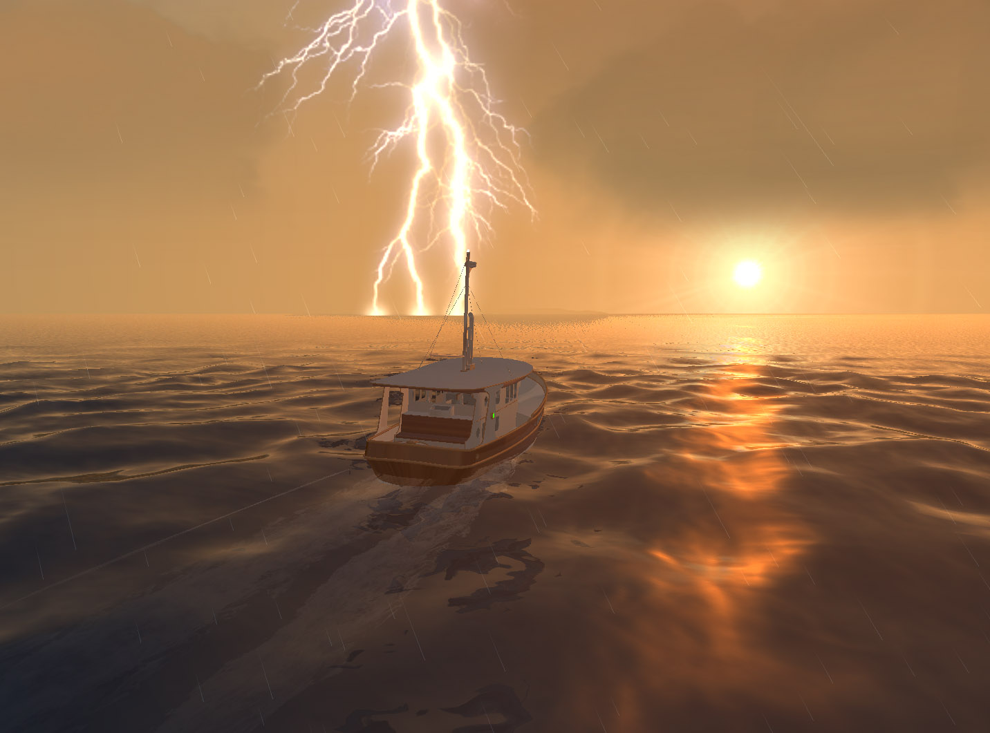
LIGHTNING...!
Strike Attenuation Strategies For Boats
Valdemar in the Aegean - Click Image to EnlargeCopyright 2002 - 2010 Michael Kasten
Why Should We Care...?
According to published reports, in the US out of the annual average of about 100 deaths due to lightning, approximately 13 are aboard boats. Suffice it to say that if lightning is a hazard where your boat will be used, a plan should be developed to deal with the possibility of a direct strike. In the Pacific Northwest lightning is relatively rare. In Florida, some areas annually have more than fifty strikes per square mile..!
According to the well known lightning researcher Ewen Thompson, lightning can develop on the order of one hundred million volts, peak currents of tens of thousands of amps, and generate temperatures of some fifty five thousand degrees. Fortunately, it lasts only a fraction of a second, but within that time it can be deadly and / or very destructive.
EMP..!
A lightning strike involves an extremely rapid change in an electric current, generating a momentary but extremely powerful magnetic field. This electro-magnetic pulse (EMP) will readily induce currents in adjacent wiring. Currents induced in wires by the EMP from a lightning strike may do some very weird things, such as fry every piece of electronics aboard. A strike nearby or on another boat can fry the electronics aboard your boat without even requiring an electrical connection or direct strike.
A direct or nearby strike may have a radical and permanent influence on the compass, and may require that it be completely re-calibrated. Strikes have been known to erase all the cassette tapes on a boat! Consider what would happen to other magnetic media, such as your hard drive! Sensitive electronics hardly stand a chance.
An issue that has recently been made public is that all of the new electronically controlled diesel engines are quite vulnerable, as compared to the older fully mechanical diesels which will happily run just fine without even being connected to anything electrical. If a strike fries the electronic control module on the engine as well as your communications electronics, you are sort of up the creek without a paddle. You'll be dead in the water and you won't be able to call for assistance. This is a fairly good argument in favor of having sails...!
So What Can We Do...?
It seems undesirable, at best, to invite a lightning strike to preferentially pass through the interior of your boat...! Lightning actually prefers to travel along the surface of objects. A lightning protection system will therefore consist of a robust "primary path" designed to safely conduct a direct strike to ground, and a secondary system designed to accommodate alternate pathways to ground (e.g. shrouds) and to protect a variety of metal objects aboard (e.g. the engine). The backbone, or primary path, will consist of a few basic components:
- An air terminal or terminals connected to:
- A robust conductor or conductors leading vertically in a straight path to:
- A grounding plate or grounding strip immersed in the water, and ideally to:
- A perimeter array of grounding, or "exit" terminals.
The latter item is a recent addition, based on Ewen Thompson's most recent research which suggests that the grounding plate should be augmented by the use of perimeter "grounding terminals" in order to mitigate the possibility of side flashes, and to more effectively dissipate a direct strike outward onto the surface of the water where it wants to go, rather than trying to direct the strike down into the water via the ground plate. This makes ultimate sense, given that lightning prefers to travel on the surface of any conductor, thus the effectiveness of a "Faraday Cage" - as described below.
Air Terminal
Typical recommendations suggest that the top-most end of the air terminal should be sharply pointed. However recent research by Professor Charles Moore suggests that in the event of a strike, a rounded end on the air terminal will intercept the lightning more effectively than a sharp spike, with the ideal radius of curvature being between 3/16 and 1/2 inch (5 to 12 mm). For the air terminal, a 1/2 inch or 5/8 inch (12 mm to 16mm) rod is recommended rather than a thin "antenna" sized air terminal which doesn't have sufficient sectional area to survive a strike.
It has been shown that multiple air terminals are more effective than one. For example on the superstructure of a motor yacht or on the top of each mast.
Several well-funded research projects have called into question the concept that lightning "dissipators" have any real benefit for boats, casting serious doubt on the effectiveness of a stainless "bristly brush" to help prevent a strike by dissipating an accumulating charge.
Cone of Protection
As a general rule, the air terminal should be at least 6" higher than anything else nearby, and should project well above everything within a 90° cone shaped zone extending downward from the top of the air terminal in all directions. This cone shaped zone extends 45° from the vertical (half of the 90° cone) in all directions with the apex at the top of the air terminal. From the top of the air terminal downward, this 90° "cone of protection" spreads out, and ideally will entirely enclose the boat. Inside the cone of protection, there will be relative - but not absolute - safety. This is the zone within which lightning will be preferentially attracted to the air terminal.
In other words, lightning that would in the absence of the air terminal, strike within the region bounded by the cone of protection, is supposed to instead strike the air terminal at the apex of the cone. The apparent mechanism for this phenomenon is that the top of the lightning rod launches an upward-going discharge to meet the downward-going lightning stepped-leader before other objects within the cone of protection can do so. Professor Moore's research suggests that a rounded tip on the air terminal can do this more effectively than a sharpened spike.
If any parts of the boat extend outside of this 90° "cone of protection" there should be additional "perimeter" air terminals, say at bow or stern or at the ends of the superstructure. Two or more air terminals will provide better protection than a single air terminal, since there may be smaller lightning discharges near the main strike.
A larger 138° cone of protection is presumed to exist by lightning researcher Ewen Thomson via his analysis of numerous instances of lightning strikes to boats.
(Ewen Thompson's results are published in a paper entitled, A Critical Assessment of the US Code for Lightning Protection of Boats, presented to an international conference of electrical engineers during May 1991. For an up to date review of Ewen M. Thompson's excellent research on Lightning, please see the links at the end of this article...)
Conductors
It is critical that the primary conductor of the lightning protection system, the path from the top-most end of the system to the water, be as robust as it can be made, be as direct as possible, and that it use long radii rather than sharp bends along the way to the grounding plate. The connections must offer low electrical resistance, or the heat created by the energy of a strike may instantly melt the connection.
Ewen Thompson's research suggests that all conductors be a minimum of #4 AWG copper (21 mm2 or 0.0326 in2). More recently, Thompson encourages even larger conductors (58 mm2- 0.09 in2). The ABYC recommends a minimum of a #4 AWG copper wire for the primary lightning protection system conductor, and a minimum of a #6 AWG copper wire for secondary conductors. Tinned wire is recommended, as always on boats.
A boat with a metal mast that is stepped on the keel will allow one of the conductors to be the mast itself, with a direct connection to the air terminal at the top, and a substantial wire connection to the grounding plate at the bottom. With a wood mast, the shrouds and stays will become the down-conductors, with each chainplate attached to a "grounding electrode" as described below. A bronze sail track on a wood mast should be considered to be a conductor and it should be made continuous via mechanical, brazed or soldered connections, then attached to the air terminal and to the grounding plate. It must have at least the sectional area of a #4 AWG copper wire, or larger. In each case, electrical continuity must be assured from the air terminal at the masthead to the grounding plate or grounding strip in the water.
Other types of conductors need to be considered: Per the ABYC, a carbon fiber reinforced wood mast or a carbon fiber reinforced composite mast will not be treated as though it is a conductor. However it should be mentioned that a continuous CF rod will certainly conduct, therefore any such CF reinforcement should be bonded to the grounding plate. Stainless is not an especially good conductor, but a stainless sail track will conduct and should be attached to the grounding plate. The ABYC states: "every metal shroud and stay shall be connected from the chain plate directly to the ground plate or ground strip with a conductor equal to at least #6 AWG copper. Where the system consists of multiple shrouds, stays, and mast, they shall have an aggregate conductivity of no less than a #4 AWG copper conductor."
A traditionally rigged vessel, having fully insulated shrouds due to service and leather at the mast, and possibly the use of deadeyes and lanyards at the deck, is a separate case. Here, if the mast is made of wood there must be a separate conductor provided, possibly a #4 or larger copper wire routed into the mast.
The ABYC rule states: "Large metal objects such as tanks, engines, deck winches, stoves, etc, within 6 feet of any lightning conductor shall be interconnected by means of a lightning conductor at least equal to #6 AWG copper. To minimize flow of lightning discharge current through engine bearings, it may be preferable to bond engine blocks directly to the grounding plate or grounding strip rather than to an intermediate point on the lightning protection system. To minimize side flashes and the induction of high voltage to the boat's wiring, lightning conductors in proximity to the boat's wiring shall not be routed in parallel to the boat's wiring."
The ABYC further states: "...a lightning system conductor shall not form a bend of less than 90° and it shall not have a bend radius less than 8 inches."
The arrangement of the "down conductors" should be given careful consideration. To bring a direct lightning strike down through the boat, say via the mast, has been found to be problematic in that the risk of side flashes is increased. For example on a fiberglass boat if the lightning were to also travel down the shrouds, this could encourage a side flash from the chain plates to the mast base, potentially endangering anyone inside the boat who may become part of the side flash pathway.
The by-words for lightning conductors are robust, direct, and having no sharp bends.
Grounding Strips
A grounding plate is considered to be the "exit terminal" in a lightning protection scheme. Thompson states, as does the ABYC, that the actual form factor of the ground plate is important. A grounding plate or strip with sharp corners or points will initiate streamers at a lower voltage and result in a lowering of grounding resistance at a lower current than will a smooth or round edged plate. In other words, the edges of the external grounding plate or strip need to be sharp, exposed, not caulked and not faired into the adjoining area.
The ABYC states: "An exterior grounding plate of copper, copper alloys, stainless steel, or aluminum may be provided by means of a plate which has an area of at least one square foot." Ewen Thompson's research indicates that in salt water, a grounding plate of one square foot in area is probably sufficient, but that in fresh water even two square feet or more may not be enough to provide a sufficiently low resistance in the event of a direct strike. If the grounding plate is not large enough, the result will be that a lightning strike will seek additional pathways to ground, and the danger of side flashes will be dramatically increased, along with possible severe damage to the hull, equipment, and people.
A grounding plate should be solid, rather than the sintered bronze type often used as radio grounds. The sponge-like structure of the sintered bronze plates may, in the event of a strike, allow the instant formation of steam, which could blow the plate apart, resulting in possible severe damage to the surrounding hull.
Thompson does not consider a grounding plate to be the ideal shape for dissipating a strike, nor does he consider its typical location near the keel to be optimum. This is in part because a square plate has a limited amount of "edge" but also because of the tendency of lightning to seek the water's surface. Rather than using a square grounding plate located down low, Thompson favors using long grounding strips, located closer to the water's surface.
Per Thompson's recommendations, the grounding strip or strips should start near the base of the primary conductor (in most cases probably the mast) and extend aft towards the motor, with the primary "down conductor" connected directly to the forward end of the grounding strip, and the aft end of the strip directly connected to the motor.
The ABYC also suggests the use of a grounding strip rather than a plate. The ABYC rule states: "A grounding strip shall have a minimum thickness of 3/16 inch (5 mm), and a minimum width of 3/4 inch (19 mm)." A strip approximately one inch (25 mm) wide and 12 feet long (3.7 m) has nearly six times the amount of edge area exposed to the water, which will improve the dissipation of charges. Per the ABYC, "The grounding strip, if used, shall extend from a point directly below the lightning protection mast, toward the aft end of the boat, where a direct connection can be made to the boat's engine."
Aside from an external ballast keel, the propeller probably represents the largest underwater mass of bare metal, and consequently an excellent ground. It is therefore desirable for the engine block to be connected to the lightning grounding plate or grounding strip via a heavy and direct conductor. This should be done in order to reduce the potential for a side flash to the engine where the strike would be seeking ground via the propeller. This could possibly prevent damage to the engine.
The grounding plates or strips must not be painted. If the grounding plate or strip is copper or bronze, the natural antifouling qualities of the copper will keep it from fouling. However if the grounding strip or plate is attached to the electrical bonding system, or directly to a zinc anode, the natural antifouling will be eliminated and the plate will quickly foul.
On a boat with an external ballast keel, the keel itself might seem like an ideal lightning ground. However, if an external ballast keel is used, an area of the surface of the ballast would have to be kept bare in order to dissipate a strike, and it would also need to have "edges." That strategy would not be entirely practical even with a lead keel, since the exposed lead area will foul fairly quickly. Therefore, even if there is external lead ballast, it is preferable to use a grounding strip.
Equalization Bus
On a fiberglass or wood boat, ABYC recommends that an equalization bus be installed on the inside parallel to the exterior grounding strip. ABYC says, "An equalization bus on the inside of the boat, paralleling the grounding strip on the outside of the boat, may be used as the lightning ground conductor." ABYC encourages use of two bolts at each end of the external grounding strip, extending between the external strip and the internal equalization bus, a metal strap inside the boat substantially parallel to the exterior lightning grounding strip, and connected to the lightning grounding strip at each end.
Secondary lightning conductors can be connected to this equalization bus.
Side Flashes
The possibility of 'side flashes' has been mentioned. A side flash is defined by Ewen Thompson as being "any discharge occurring during a lightning strike that involves the formation of a spark channel from any source other than an air terminal or a grounding electrode."
Lightning strikes may involve side flashes to other metal objects that provide a convenient alternate path for the discharge. Side flashes are encouraged by an insufficient path to ground, or an insufficient area of the grounding plates or strips. Side flashes can create a chain from one item to the next on the way to ground. Side flashes are most prevalent in fresh water.
In fact, Ewen Thompson's findings suggest that side-flashes are inevitable in fresh water, but they are much less likely in salt water, assuming that in both cases there is a lightning protection system aboard. His survey results show a much higher incidence of serious hull damage in fresh water than in salt water.
Thompson distinguishes between two types of side flashes:
- Internal side flash: A sideflash that forms between two conductors on or inside the boat. Basically any metal object onboard.
- External side flash: A sideflash that forms between an onboard conductor and the water.
Bonding Conductors
To minimize the potential for side flashes, ABYC recommends use of a secondary protection system which will ideally involve all the metal objects aboard a boat that are larger than a toaster (exceeding one foot in any direction). Per ABYC these metal objects are to be connected to the lightening protection system equalization bus via secondary "bonding" conductors.
The ABYC states: "Seacocks and through hull fittings, if connected to the lighting ground system shall not be connected to the main down-conductor. They shall instead be connected to the grounding strip or plate, or to the internal equalization bus." Connecting these metal components to the lightning protection system will serve to equalize the built up potential and reduce the likelihood of an internal side flash. However, as Thompson points out this also increases the risk that external side flashes may occur from any of the bonded fittings to the water. It is specifically the issue of external side flashes that are addressed by Thompson's auxiliary grounding terminals, described below.
We are faced with a possible point of confusion here - we are not referring to the electrical bonding system, which hardly qualifies as a lightning conductor. Neither is the electrical bonding wire or strap adequate to handle the intense discharge during a direct strike. We also know that if the bonding system is asked to participate in the lightning protection system, the copper grounding plate or grounding strip will lose its natural antifouling qualities due to action by the zinc anodes. On that basis, the secondary bonding conductors in the lightning protection system might kept separated from the corrosion protection bonding system. However per the ABYC, the negative terminal of the DC electrical system is to be bonded to the lightning protection equalization bus.
On reviewing Ewen Thompson's lightning protection strategies, he arranges the secondary lightning protection bonding conductors more or less as a "Faraday cage" around the perimeter of the boat, tied to the large metal objects, and leading downward to the equalization bus, and therefore to the grounding plate or strip. Thompson encourages the use of:
- Multiple air terminals
- An interconnected grid of down conductors placed around the perimeter
- A loop conductor that completely encircles the boat well above the waterline
- A grounding strip
- An array of auxiliary grounding terminals, described as follows:
Auxiliary Grounding Terminals
In order to mitigate side flashes between the various "down conductors" (masts, shrouds, chainplates, etc.) Ewen Thompson recommends augmenting the grounding plates or grounding strips with multiple "supplemental grounding electrodes." This system uses an array of electrodes electrically isolated from the hull and located just above the surface of the water.
In Thompson's and others' observations of actual damage done by lightning on unprotected boats, the preferred "exit" path is typically at or close to the waterline. Thus, lightning is observed to have an affinity for the water's surface. Since that seems to be the preferred path, Thompson's "grounding electrodes" simply encourage that path in order to more effectively dissipate the charge of a direct strike.
These simple devices were actually "patented" by Thompson in 2001 under the name of SiedarcTM. Thompson offers a variety of different types pre-configured so that they can be quickly installed. This is great stuff in my view, because these simple "grounding electrodes" take advantage of basic physics and "off the shelf" available parts.
These grounding electrodes do not involve anything fancy at all. They consist of a standard off-the-shelf bronze or stainless through-hull fitting of the type and size that is normally used as a drain. Then an "electrode" is bonded into the center axis of the fitting with epoxy, thus isolating the "electrode" electrically from the through-hull fitting. The electrode has the same specification as the air terminal - a 1/2 inch diameter rod, in this case bronze. The outer end of the electrode is pointed, and positioned so that the point is just proud of the extremity of the through-hull fitting, and so that its point sticks out of the epoxy fill. On the inboard end, the electrodes are connected to the lightning bonding conductors.
These are located wherever there is the likelihood of a flash to the water, such as at the base of each of the shrouds and stays where it has been observed that flashes tend to occur, "seeking" the water's surface. In other words, they are designed to provide a "preferred path" that mimics the behavior of lightning in documented events, to provide a path toward ground that allows a strike to dissipate onto the surface of the water, where lightning seems to seek.
These auxiliary grounding electrodes do not replace the requirement for having a grounding strip immersed in the water. Instead, they are used in addition to the grounding strip to augment the lightning protection system. Their purpose being to minimize the likelihood of side flashes, and to form a much more effective "grounding grid" to dissipate a strike.
Thompson's strategy is sufficiently well accepted that he was invited to help write the National Fire Protection Association's Lightning Protection Standard for watercraft. The ABYC as well is studying Thompson's auxiliary grounding terminals for possible inclusion in a future standard - however the ABYC is moving rather slowly on this.
Faraday Cage
Faraday discovered that lightning tends to prefer to run along the outside surface of objects, and that a metal "cage" could be built that would protect anything located inside of but separate from the cage. A logical approach will take advantage of this natural tendency. On a fiberglass boat, Ewen Thompson's strategy is to arrange the system of secondary lightning bonding conductors more or less as a "cage" surrounding the boat, leading down to a series of auxiliary grounding electrodes.
For lightning protection, the ABYC encourages the use of external shielding to create a 'Faraday Cage' around instruments. The ABYC states: "Wherever possible, electronic equipment should be enclosed in metal cabinets that are connected to the lightning grounding system. Surge suppression devices should be installed on all wiring entering or leaving electronic equipment."
With a metal boat, the hull itself makes an excellent protective Faraday cage as well as an excellent conductor. The ABYC states that aboard a metal boat, "If there is electrical continuity between metal hulls and masts, or other metallic superstructures of adequate height, then no further protection against lightning is necessary."
However on a metal boat there must still be one or more air terminals at the top, attached directly to an aluminum mast or to the metal superstructure. The best strategy aboard a metal boat will be to encourage the hull itself to be integral with the primary conductor. In other words, to create an effective Faraday cage it seems appropriate to have a #4 AWG or larger copper jumper attached from the primary down-conductors (mast, shrouds, etc.) to the deck our house top, to encourage the lightning to go around the outside of the hull, rather than through the boat's interior.
Still, the hull may not serve as an adequate lightning grounding surface due to the hull being completely enclosed within an epoxy skin. Even considering the zincs as grounding plates, lightning protection will not be as intended, since the area of the zincs may not be sufficient, and the zincs will not have the requisite sharp edges in order to propagate sparks that will dissipate the strike. Therefore it also seems appropriate to include a grounding strip, with a #4 AWG or larger copper jumper connected in a straight line from the mast to the grounding plate or grounding strips located near the base of the mast.
In the case of a metal boat, the hull serves as the Faraday cage, an integral part of the primary conductor, an equalization bus and a bonding conductor all in one. The remaining objective is to dissipate a strike safely. There is good justification to use a grounding strip, as well as supplemental grounding electrodes located just above the waterline, and in this case attaching the electrodes on the inside directly to the boat's metal structure.
During an Electrical Storm
In an electrical storm we will be safest if we stay inside the boat, away from all metal parts, such as metal masts, shrouds, lifelines, engines, metal tanks, stoves, water pipes, faucets, sinks, electronic gear, inside ballast, spare anchors, or chain. We should especially stay away from any area between large metal parts. Not so easy to accomplish...! But if the vessel has employed the kind of system advocated by Ewen Thompson and the new NFPA Lightning Protection Standard, we will have a much better chance.
Aboard a metal boat, the boat itself forms a protective Faraday Cage and we should simply just stay inside if at all possible.
And then we had best observe Bre'r Fox' advice closely: "Lay low, an' don't say nuffin!"
Summary
From the above, we can readily see that the lightning attenuation issues aboard a boat of any material are in no way addressed by the boat's electrical bonding system. If a lightning attenuation system is to be effective, the above details are quite important. A system that is poorly done or possibly compromised by a failed connector could actually make the situation worse, for example by encouraging side flashes that could damage the boat or its equipment or start a fire or injure or even kill someone onboard.
The ABYC notes that even if their new Lightning Protection Standard is employed, complete protection from equipment damage or personal injury is not implied, and that a lightning protection system offers no protection when the boat is out of the water.
The ABYC further notes that protection of persons and small craft from lightning is dependent on a combination of design and maintenance of equipment, and on personnel behavior. The ABYC guide is general in nature, and pointedly states that in view of the wide variation in structural design of boats, and the unpredictable nature of lightning, specific recommendations cannot be made to cover all cases.
Needless to say, aboard a boat, any strike is to be considered dangerous. Protection requirements for a boat should be more stringent than those for buildings, since a failure of the protection system is more likely to result in personal injury aboard a boat. A failure rate which may be acceptable on buildings is clearly unacceptable on a boat in mid-ocean.
This discourse on lightning is not intended to recommend a specific approach. It is presented here simply to introduce the magnitude of the problem. Lightning is dangerous and unpredictable. Experts and standards bodies have not reached consensus on the subject. It is up to your own best judgment to choose what will work best board your own boat!
If it were my boat...? Without question I'd consult with Ewen Thompson to help design and create the lightning protection system. I definitely encourage anyone interested in this subject to review Ewen Thompson's web pages, a few of which are linked below.
Ewen Thompson's Lightning Website | Non-Technical Article on Lightning Grounding
The Science of Yacht Lightning Protection | Technical Lightning Grounding Information
Please see the AVAILABLE BOAT PLANS web page.
Home | Intro | Our Design Process | Stock Design Info | Motor Yacht Designs | Sailing Yacht Designs | Prototype Designs
Plans List | Articles | Our CAD Design Stream | Maxsurf | News..! | SITE MAP..! | Site Search | Design Team | Contact Us